The design goal of this project was to build the best possible base station antenna, given the the landscape available: standard 40+ meters lot, with few tall fir trees around. More exactly:
- preferrably omnidirectional coverage
- full legal limit 1.5kWt for possible future rig expansion
- flexible support by trees, with no tower
- reliability, both mechanical and electrical
- single coax obviously
- not relying much on tuner, although tuner is a part of rig
- one man should be able to bring antenna down for maintenance and lift it up
Obvious choice was the multi-band fan dipole. Omnidirectional coverage is impossible with the ideal dipole, but inverted-V design in real environment helps. Off-Center-Fed dipoles were excluded, because on higher bands they have dead zones, which not many hams mention. Originally antenna has been built as the five-band dipole, then two top bands were removed after one year of operation.
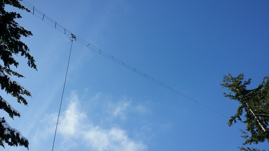
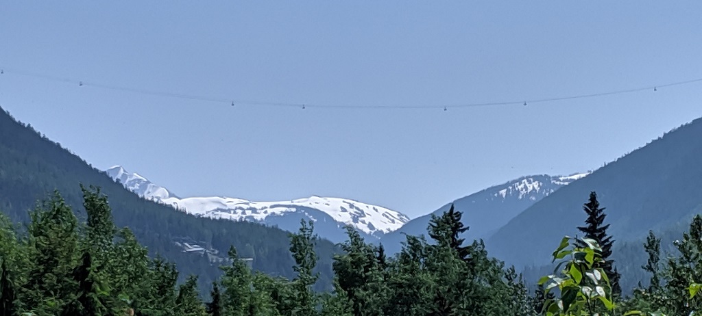
Tri-band inverted-V fan dipole: final design, operational now in 2017 (click to enlarge):
Final dimensions of the current tri-band dipole. Risers are those pigtail pieces of wire, connecting the wing with balun (they are included in the total length).
Band |
final length of both wings together, in cm |
left wing |
left riser |
right riser |
right wing |
80 m |
3734 |
1800 |
67 |
68 |
1799 |
40 m |
1958 |
955 |
24 |
24 |
955 |
20 m |
1023 |
478.5 |
33 |
33 |
478.5 |
|
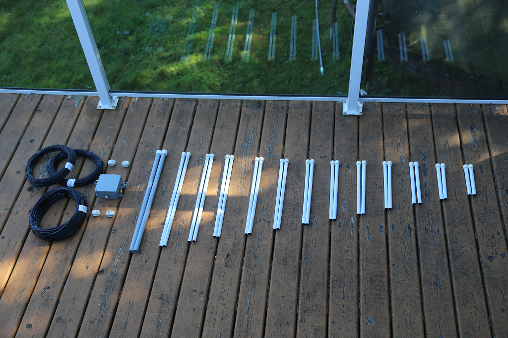
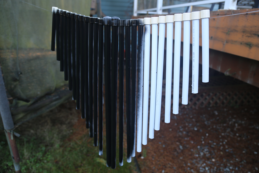
Spacers have been cut from the plastic pipes, with caps on top (not on the bottom). The first two spacers are stronger than others, because they have to route all wires to the balun. Flex-Weave #12 AWG wire is used for all bands, although for future builds only 80 m wire can be #12 AWG, others can be thinner, at least #14 AWG or less. 80 m wire carries all the load. Especially in my case, when it was no central support initially, so all wires of all bands were hanging on 80 m wire. It was actually U-shaped dipole, "Non-Inverted U".
Thick 5/16" Dacrone rope is used to lift antenna up and hold it year around. For one-man operation, this rope must be thick. It was brought to the tree top with a slingshot.
 |
 |
This spreadsheet shows the drill points, measured from the top of spacers. It was taken as granted from some website, that minimal distance between wires must be at least 5.5" (135 mm), to have not-so-narrow bandwidth. With caps height of 16 mm, excluding the first two of 21 mm, the following table has been created. It matches the no-scale right wing drawing above. The bottom line shows the total length of each spacer - where to cut it off.
With a lot of work for 80-40-20 wires, it was decided to try 10 and 6 meter bands as well, since it was very easy to add those short wires. So with 5 bands, the distance between wires was 5.5". Later, 10 and 6 meters wires have been cut off, so distance between wires now is 11". This can be done right from the beginning.
Spacer number |
1 |
2 |
3 |
4 |
5 |
6 |
7 |
8 |
9 |
10 |
11 |
12 |
13 |
|
X coordinate, m |
0.00 |
0.80 |
1.65 |
2.50 |
3.30 |
4.15 |
5.00 |
5.83 |
6.67 |
7.50 |
8.34 |
9.17 |
10.00 |
|
| Band | X interval, m |
0.800 |
0.850 |
0.850 |
0.800 |
0.850 |
0.850 |
0.834 |
0.834 |
0.834 |
0.834 |
0.834 |
0.834 |
|
80 m |
space from 80m wire, mm |
0 |
0 |
0 |
0 |
0 |
0 |
0 |
0 |
0 |
0 |
0 |
0 |
0 |
to drill, mm: |
21 |
16 |
16 |
16 |
16 |
16 |
16 |
16 |
16 |
16 |
16 |
16 |
16 |
|
6 m |
space from 80m wire, mm |
135 |
118 |
101 |
shifted 1/4 |
|||||||||
to drill, mm: |
156 |
134 |
117 |
|||||||||||
20 m |
space from 80m wire, mm |
270 |
248 |
225 |
202 |
181 |
158 |
135 |
||||||
to drill, mm: |
291 |
264 |
241 |
218 |
197 |
174 |
151 |
|||||||
10 m |
space from 80m wire, mm |
404 |
377 |
349 |
320 |
shifted 3/4 | ||||||||
to drill, mm: |
425 |
393 |
365 |
336 |
||||||||||
40 m |
space from 80m wire, mm |
539 |
507 |
472 |
438 |
406 |
371 |
337 |
303 |
270 |
236 |
202 |
168 |
135 |
to drill, mm: |
560 |
523 |
488 |
454 |
422 |
387 |
353 |
319 |
286 |
252 |
218 |
184 |
151 |
|
total spacer length |
576 |
539 |
504 |
470 |
438 |
403 |
369 |
335 |
302 |
268 |
234 |
200 |
167 |
|
|
|
|
|
|
|
|
|
|
|

